

[*]Step 18 ââ¬â Pull the switch wire harness connectors out of the crank hole in the plastic and reinstall the rest of the plastic.
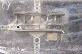
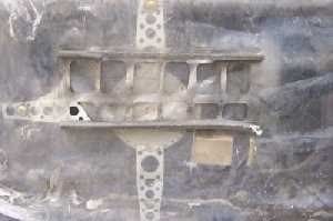
[*]Step 19 ââ¬â Now is the time to get rid of the butt freezer option installed on all hardbodys. Notice in the pic of the plastic over the motor the slits to let air pass into the cabin. They are supposed to make closing the doors easier by allowing pressure to escape. All they do is freeze your butt off when you crack the window in the winter. Take some tape and cover the slits.
[*]Step 20 ââ¬â Route the wire harness over the lower blower housing mounting location and push it behind the center column to exit in the driverââ¬â¢s floorboard
[*]Step 21 ââ¬â Reinstall the blower housing. To keep the seal between it and the coil in location reach inside the housing as you install it and hold the seal in location. Route the wire that controls the blower housing door back along the vent tunnel.
[*]Step 22 ââ¬â Reinstall the lower side kick panel.
[*]Step 23 ââ¬â Reinstall the blower remembering to reconnect the harness and drain hose.
[*]Step 24 ââ¬â Reinstall the panel behind the glove box.
[*]Step 25 ââ¬â Reinstall the glove box.
[*]Step 26 ââ¬â Have a beer, youââ¬â¢ve worked really hard. Run out of time? Feed the window switch wire connectors back into the door, snap the door panel back on and finish another day. Pull the wire harness out of the driverââ¬â¢s floorboard and route it in front of the center column and let your passengers deal with it until you finish the job. Sorry you canââ¬â¢t roll down the window yet and I hope it wasnââ¬â¢t rolled down when you started (remember the warning in step 8?) or you might get a little wet, cold or hot depending on the weather.
[*]Step 27 ââ¬â Ready for some more wire harness routing? Itââ¬â¢s not as bad on the driverââ¬â¢s side (but not by much). Remove the lower side kick panel as in step 4.
[*]Step 28 ââ¬â Remove the two screws that hold the knee kick panel under the steering wheel in place.
[*]Step 29 ââ¬â Remove the cover for the park brake rod if dash mounted.
[*]Step 30 ââ¬â Remove the knee kick panel.
[*]Step 31 ââ¬â Unbolt the fuse block so you can get to the door jamb grommet.
[*]Step 32 - Route the wire harness over the park brake (if dash mounted) and tie strap it up against the fire wall using the park brake rod as an anchor so that it doesnââ¬â¢t get caught in park brake.
[*]Step 33 ââ¬â Route the harness through the holes in each side of the steer column mounting bracket.
[*]Step 34 ââ¬â Route the wire harness over the fuse block harness.
[*]Step 35 ââ¬â Repeat steps 6 through 19.
[*]Step 36 ââ¬â Wrap up any excess harness and wire tie above the fuse block.
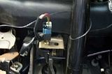
[*]Step 37 ââ¬â Time to get power to this setup. This step is done from inside the vehicle. Remove the steer column wire wall cover. Drill a hole 7/16â⬠through the fire wall below and to the right of the steer column.
[*]Step 38 ââ¬â Insert one of the extra rubber grommets that came with the window kit into the hole so that your power wire doesnââ¬â¢t get worn and short out.
[*]Step 39 ââ¬â From the left hand side of the steer column route the relay main power wire back along the path of the window harness but just through the left hand hole in the steer column mounting bracket. Wire tie the wire to the steer column.
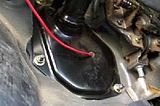
[*]Step 40 ââ¬â From inside the vehicle feed the relay main power wire out of the hole into the engine compartment.
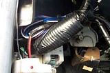
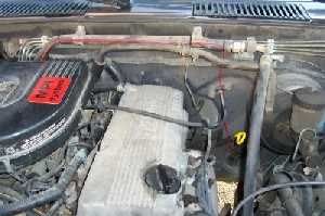
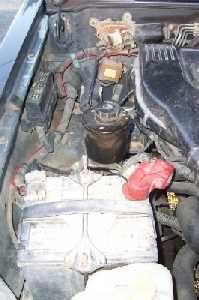
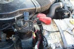
[*]Step 41 ââ¬â In the engine compartment Route the main power wire up to the AC and heater tubes running across the compartment. Wire tie the wire to the tubes and run to the passenger side.

[*]Step 42 ââ¬â Come off of the AC and heater tubes and wire tie the power wire to the relay harness.
[*]Step 43 ââ¬â Cut the wire to length to go to the positive battery post. Attach a 30 amp inline fuse. Weââ¬â¢ll attach it to the post after we finish wiring on the inside.

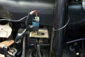
[*]Step 44 ââ¬â Remove the bottom bolt that holds the fuse block bracket to the door jamb. Install the relay using this bolt to that location.
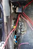
[*]Step 45 ââ¬â Below that bolt is a ground screw with a ground wire attached to it. Remove the screw and ground the relay to that screw. Ground the window wire harness to that screw. Reinstall the screw.
[*]Step 46 ââ¬â Remove the stereo fuse from the fuse block and install the Add-A-Circuit in that spot. Put 10 amp fuses in both ports.
[*]Step 47 ââ¬â Connect the relay trip wire to the Add-A-Circuit wire. This way whenever you turn your key to ACC the windows will have power.
[*]Step 48 ââ¬â Connect the relay positive wires to the window wire harness positive wires.
[*]Step 49 ââ¬â Connect the relay main power harness to the positive battery post. Just loosen the terminal, remove it, place the wire against the post and reinstall the terminal.
[*]Step 50 ââ¬â Itââ¬â¢s test time!. Put a switch on the passenger door window wire harness and switches on the driverââ¬â¢s door window wire harness. Crap! The battery is run down (remember the warning in step 1?) . Find somebody to jump the battery. Try out your windows. If it doesnââ¬â¢t work use a tester from the relay main power wire to the relay, from the Add-A-Circuit to the relay on key at ACC, from the relay to the outgoing power and from the outgoing power to the window motors and switches to find the break.
[*]Step 51 ââ¬â Reinstall the knew kick panel.
[*]Step 52 ââ¬â Reinstall the two screws that hold the knee kick panel under the steering wheel in place.
[*]Step 53 ââ¬â Reinstall the cover for the park brake rod if dash mounted.
[*]Step 54 ââ¬â Reinstall the lower side kick panel as in step 22.
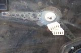
[*]Step 55 ââ¬â Alright, now to install the door panels and wrap this baby up. Take the switch housing, flip it over and make a mounting template.
[*]Step 56 ââ¬â Place template on back side of door panel and mark holes for mounting. Angle it a little and it makes a better feel and appearance. Place it so that the top is covering the old window crank hole by 3/8ââ¬. I matched it to the line melted into the door panel cover. Drill 7/64â⬠holes through the panel and mount the switch covers. Cut the panel board out into the shape of an oval towards the bottom of the switch covers to make room for the switch wires to come through.
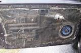
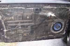
[*]Step 57 ââ¬â Replace all those broken, worn and bent Christmas tree clips in the door panel. Remove the switches from the harness. Reinstall the door panel but donââ¬â¢t snap in any clips yet. Feed the switch wire harness connectors into the switch housing and out through the switch mounting holes.
[*]Step 58 ââ¬â Attach the switches and get all of them functioning in the same manner. I like mine; push down on the back the window rolls down, push down on the front the window goes up. Press the switches down into the switch housings.
[*]Step 59 ââ¬â Starting at the top of the panel and working from underneath it get the top row of clips aligned and installed.
[*]Step 60 ââ¬â Feed any excess window switch wire harness back into the door. Reach inside the door and make sure wire routing is out of the way of mechanicals.
[*]Step 61 ââ¬â Align and install the remaining clips.
[*]Step 62 ââ¬â Reinstall the door handle surrounds.
[*]Step 63 ââ¬â Reinstall the door armrests.
[*]Step 64 ââ¬â Reinstall the door lock pullers.
continued here... http://autopia.org/forum/showthread....537#post676537
Results 1 to 1 of 1
-
02-10-2006, 06:30 PM #1


- Join Date
- Jul 2003
- Location
- Kentucky, USA
- Posts
- 316
- Post Thanks / Like

Autoeng


 Reply With Quote
Thread Information
Users Browsing this Thread
There are currently 1 users browsing this thread. (0 members and 1 guests)
Similar Threads
-
Subaru BRZ clear bra install, window tint & Wolf`s Hard Body Sealant
By Rickrack in forum Click & Brag -The Detailers ShowcaseReplies: 11Last Post: 11-03-2012, 08:26 PM -
How to - Aftermarket power window install - Part 3 of 3
By Autoeng in forum Car Interior & ElectronicsReplies: 1Last Post: 07-28-2007, 08:39 AM -
Squeaky power window glass ?
By rd_volvo in forum Car DetailingReplies: 6Last Post: 08-14-2006, 01:14 AM -
How to - Aftermarket power window install
By Autoeng in forum Car Interior & ElectronicsReplies: 0Last Post: 02-10-2006, 03:32 PM -
Power window trivia for the experts
By panamaniac in forum Car Interior & ElectronicsReplies: 6Last Post: 01-02-2005, 10:08 PM
Bookmarks